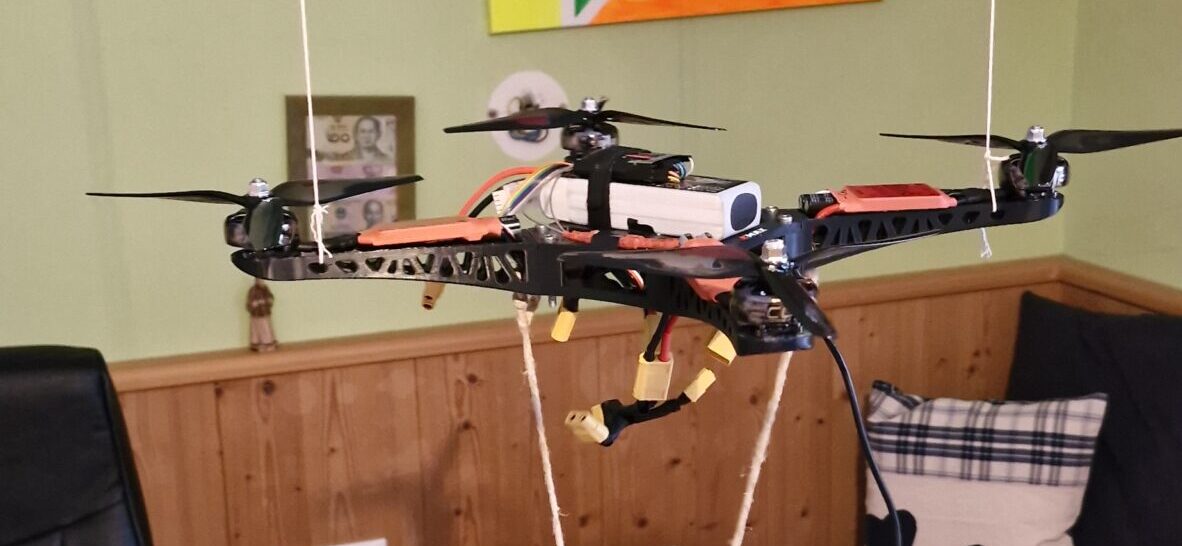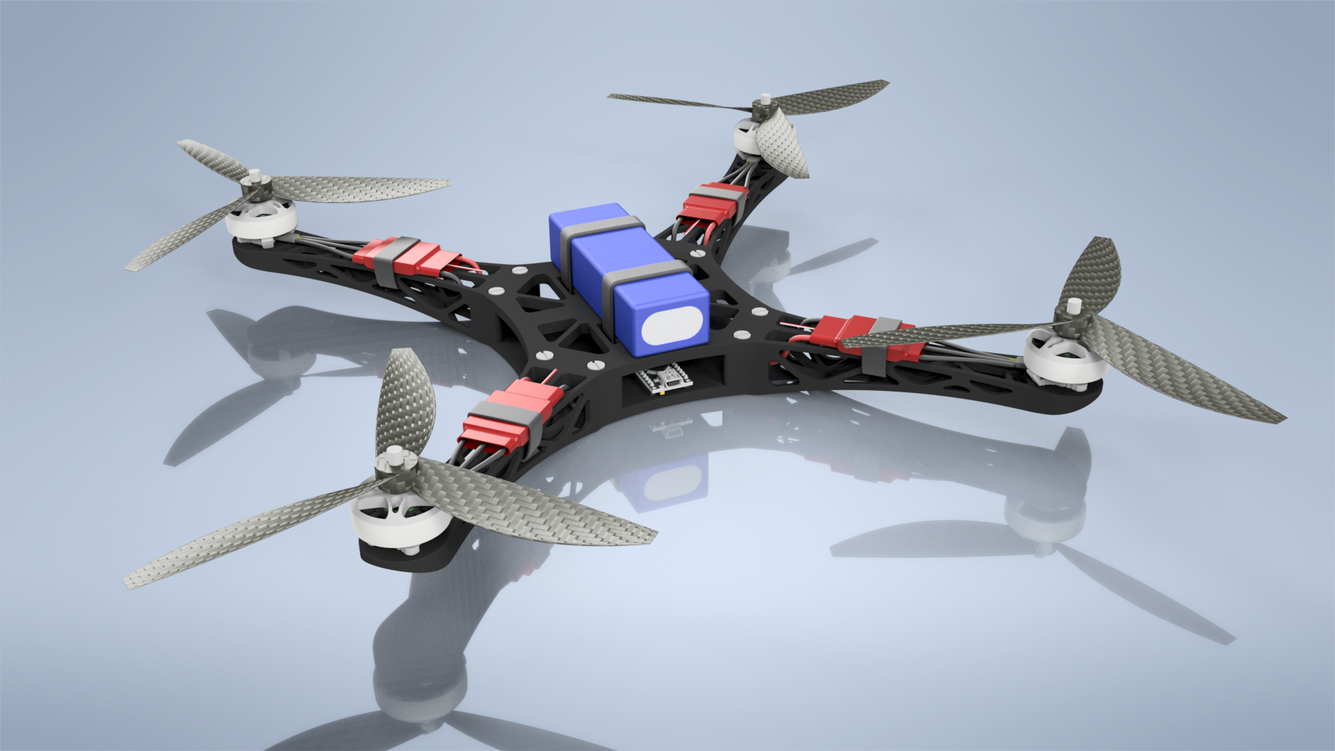
This project aims to build a drone entirely from scratch, with a primary focus on developing custom software. The aim is to better understand different control architectures for drones as well as possible state estimation techniques that are not commonly used in commercial drones.
Simulation
As a first step for this project, a simulation in Matlab Simulink was developed. The simulation is based on Mathematical Modelling of Unmanned Aerial Vehicles with Four Rotors.
The simulation was developed in order to test different control techniques as well as different state estimators for pose estimation. The video and images below illustrate the outcome of the simulation. The state estimators as well as the controllers are compared in the section "Experiments".
The simulation contains various physical influences, going from drag on different parts of the mechanics all the way to wind gusts and battery voltage drop. For further details on the simulation, feel free to get in touch!
A visualization was created using Simscape Multibody in order to get a better feeling for the drone's behaviour.
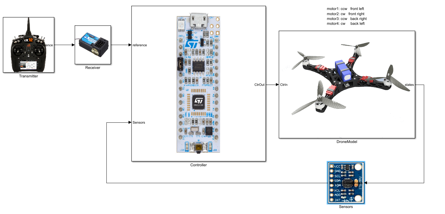
The video above shows the drone going into a hover position at 1 m height with random 3 m/s wind gusts from all directions.
The video below shows the drone flying a circle, while maintaining the correct yaw angle again with wind gusts of 3 m/s. The results were achieved using a linear Kalman Filter for the IMU and a PD controller for each DOF. The vectors displayed are a visualization of the wind force acting on the drone.
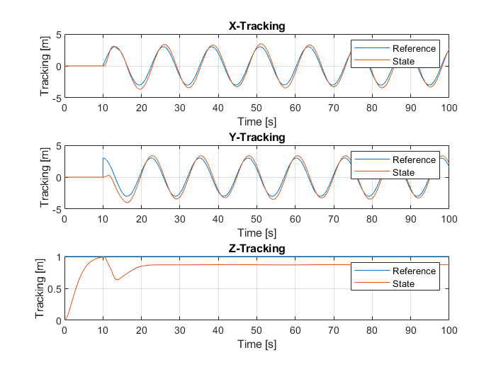
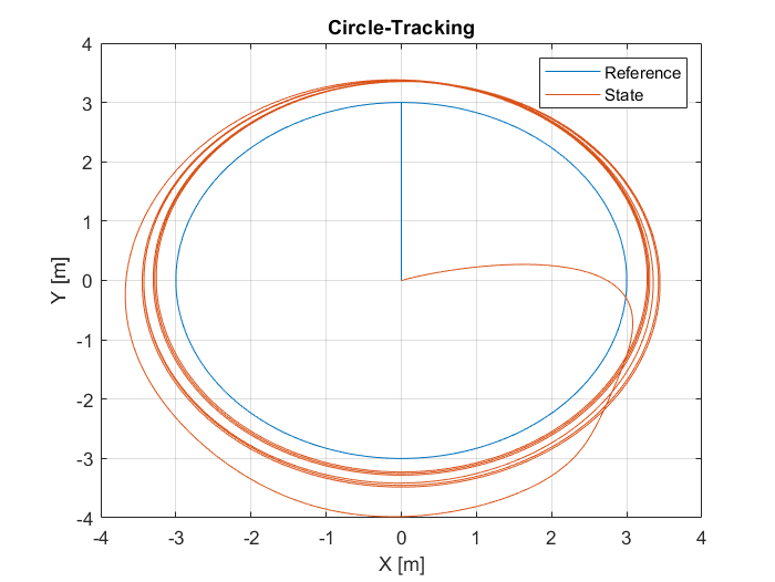
The graph above displays the result when tracking a circular trajectory on the XY-plane. The results show a substantial steady state tracking error. This could either be reduced by adding an integral term to the PD controller, or by using another control architecture. For this project, the goal is not the most lightweight or easiest-to-implement controller, but rather to learn about new controller architectures that can match or even beat the performance of a PID. Therefore, I also implemented an LQR controller as well as a nonlinear MPC in simulation. The nonlinear MPC requires a lot of computational power and is therefore only implemented in simulation. It was designed with 12 states and 4 inputs.
Hardware
Beyond the software, the drone's frame was designed and manufactured using 3D printing techniques. The electronic hardware is currently in its prototype phase and has not been optimized specifically for drone applications. Below are the components selected for the project:
Drone Controller (Brain): STM32-G431KB
Selected for its affordability, relatively high computational power (170 MHz), versatility, compact size, low power consumption, and multiple connectivity options including 4x PWM pins, SPI, and I2C interfaces.Motors: EMAX ECO II 1700 KV
Chosen based on compatibility with the propeller and battery size.Propellers: 7x3.5x3 (7-inch, 3-blade)
Designed to deliver higher thrust, as power consumption optimization was not a priority in this project.ESC (Electronic Speed Controllers): 40A PWM-compatible
Capable of handling the required current for motor control.Battery: 4S 2200 mAh
Provides sufficient power to meet the system's energy demands.IMU (Inertial Measurement Unit): Invensense GY-87
A low-cost, low-power sensor used for motion tracking and stabilization.Barometer: Bosch BMP380
Selected for its high accuracy in pressure sensing.Transmitter: Turnigy TGY-9X
Used for remote control.Receiver: Turnigy IA6C Mini
A compact and reliable receiver compatible with the transmitter.ESP32 Mini
Wi-Fi and Bluetooth link to send and receive commands and telemetryHC-SR04
Ultrasonic sensor mounted beneath the drone to measure the height close to the ground with higher precision; fused with the barometer in a Kalman filter
This integrated approach ensures a blend of custom design, prototyping, and practical component selection to achieve the project's goals.
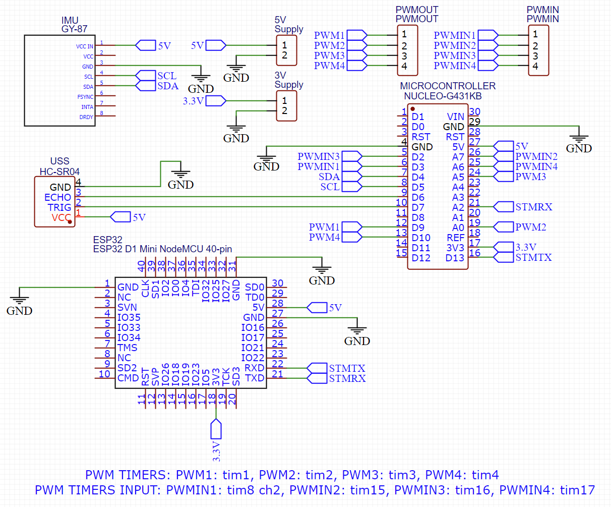
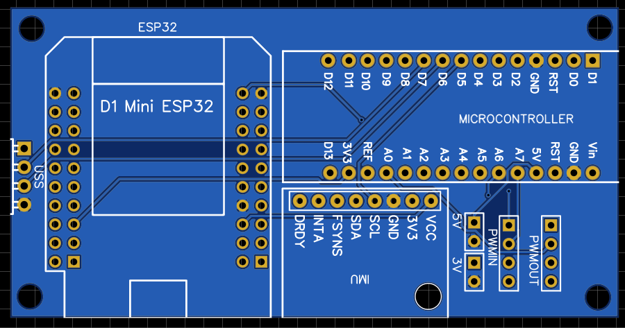
The low voltage electronics are connected as follows:
Software
All flight software runs on the STM32-G431KB (Cortex-M4F at 170 MHz, single-precision FPU, 32 KB RAM). Everything is float32 and statically allocated, with no heap. The design goal is one common interface: whichever controller is active, it outputs four virtual inputs [T, τφ, τθ, τψ] to a shared mixer, so PID, LQR and MPC can be swapped without touching the rest.
Architecture and timing
| Task | Rate | Notes |
|---|---|---|
| IMU read (I2C + DMA) | 1 kHz | Timer-triggered, processed in the DMA-complete callback |
| Attitude estimator | 1 kHz | Runs right after each IMU sample |
| Rate controller + mixer + PWM | 400–500 Hz | Limited by the PWM refresh rate the ESCs accept |
| Attitude / LQR loop | 200–500 Hz | |
| Altitude and velocity estimators | 100 Hz | Baro and ultrasonic updates arrive asynchronously |
| Outer loops (velocity, position) | 50–100 Hz | |
| RC input and ESP32 telemetry | 50 Hz | UART with DMA |
Timing is checked with the DWT cycle counter, and the CPU load of each task is streamed as telemetry.
State estimation
1. Attitude: multiplicative EKF (MEKF)
A Mahony complementary filter serves as the baseline, and an error-state EKF is the main estimator. It works on a quaternion and a gyro bias, so the filter only tracks a 6-element error state:
nominal:  q, b_g
error:    x = [δθ (3), δb_g (3)]
predict:  q ← q ⊗ exp(½ (ω_meas − b_g) dt)
F = [ −[ω−b_g]× −I ; 0 0 ] Q from gyro noise + bias random walk- Accelerometer update: compares the measured gravity direction with
R(q)ᵀ·[0 0 1]. The measurement noise is inflated with| ‖a‖ − g |, so the filter trusts the gyro during hard maneuvers and vibration. - Magnetometer update: projected onto the horizontal plane so it can only correct yaw and never corrupts roll and pitch. Motor current disturbs the compass, so its weight is reduced at high throttle, with a fallback to gyro-only yaw hold.
- Why not just a linear KF? It works well near hover, but the MEKF stays valid at large tilt angles and has no gimbal-lock issues.
2. Altitude: 4-state Kalman filter with baro offset
x = [z, v_z, b_accel, b_baro]
input:       a_z = (R(q)·a_body)_z − g          (predict at 100 Hz)
ultrasonic:  z = r·cosφ·cosθ                    (tilt-corrected, ~20 Hz)
baro: z_baro = z + b_baro (~50 Hz)- The baro reading is modeled as height plus a slowly drifting offset. While the HC-SR04 is in range (roughly 0.05 to 2 m) it anchors the height and lets the filter learn
b_baro. Above that range the baro takes over with the last learned offset, so the handover is smooth. - Ultrasonic readings go through an innovation gate (χ² test) to reject bad echoes from ground effect, props and tilted surfaces.
- The baro is covered with foam to reduce prop-wash pressure noise.
3. Horizontal velocity: drag-model pseudo-measurement
Rotor drag makes the body-frame x/y acceleration roughly proportional to body-frame velocity, a_xy ≈ −(k_d/m)·v_xy. On a quadrotor the thrust always points along body z, so whatever the sensor reads on body x and y can't come from thrust. It is almost entirely aerodynamic drag (rotor drag plus airframe drag), which at low speed is roughly linear in velocity. A 2-state velocity KF uses the rotated accelerometer for prediction and this drag relation as a measurement. It should give usable velocity damping in hover. Drift-free position still needs an optical-flow sensor (e.g. PMW3901) or GPS, which would slot in as another measurement update.
Controllers
1. Cascaded PID (flies first)
position P → velocity PID → desired acceleration → thrust vector
→ desired roll/pitch (yaw from setpoint) → attitude P → rate PID → mixer- Thrust is divided by
cosφ·cosθfor tilt compensation and gets a hover-thrust feed-forward. - The rate loop uses D-on-measurement with a low-pass filter (gyro noise) and integrator anti-windup.
2. LQR with integral action (LQI, simulation only)
- Linearized hover model with states
[x y z φ θ ψ ẋ ẏ ż p q r]and inputs[ΔT, τφ, τθ, τψ]. - The integral of position error is appended, giving 16 states. This directly addresses the steady-state tracking error seen in the circle experiment.
- Gains
Kare computed offline in MATLAB withdlqrand stored as a constantfloat K[4][16]. Runtime cost is 64 multiply-accumulates, trivial for the G431. - The linearization holds to about ±20° tilt, so tilt is clamped upstream.
3. Nonlinear MPC (simulation only)
- 12 states, 4 inputs, horizon N = 20 at 50 ms steps, real-time-iteration sequential quadratic programming (SQP).
- Constraints: thrust bounds, tilt ≤ 35°, body rates, and motor saturation.
- Why it doesn't run on the G431: the linearized dynamics per stage (
A_k,B_k) are 192 floats, so 20 stages take about 15 KB, roughly half the RAM. A realistic path is running a linear or short-horizon MPC on the ESP32 at 20 to 50 Hz as an outer loop that sends attitude and thrust setpoints, while the STM32 keeps the inner loops.
Mixer and motor output
- A quad-X mixing matrix maps
[T, τφ, τθ, τψ]to four motor thrusts. - Thrust to PWM goes through an inverse of a fitted quadratic thrust curve, scaled by
V_nom / V_battto compensate battery sag (the same effect modeled in the simulation). - On saturation, thrust is reduced first so attitude authority is preserved.
Safety
- Arming requires low throttle and a level, stationary drone.
- RC-link loss triggers a slow controlled descent and then disarm, and the independent watchdog (IWDG) cuts the motors if the control loop stalls.
- Tilt and rate limits are enforced at the mixer, regardless of which controller is active.
Loop skeleton
// Called from DMA-complete of the IMU read (1 kHz)
void imu_isr_task(void) {
    imu_sample_t s = imu_get();
    mekf_predict(&att, s.gyro, DT_1K);
    mekf_update_accel(&att, s.accel);
    if (mag_ready()) mekf_update_mag(&att, mag_get());

    if (++div_ctrl >= 2) {                 // 500 Hz
        div_ctrl = 0;
        vec4 u = ctrl_active->step(&att, &est, &sp);   // PID / LQI
        motors_write(mixer(u, vbat_scale()));
    }
    if (++div_alt >= 10) {                 // 100 Hz
        div_alt = 0;
        alt_kf_predict(&alt, world_accel_z(&att, s.accel), DT_100);
        if (sonar_new()) alt_kf_update_sonar(&alt, sonar_range(), &att);
        if (baro_new())  alt_kf_update_baro(&alt, baro_alt());
    }
}
Experiments
| Scenario | PD | PID | LQI | NMPC |
|---|---|---|---|---|
| Hover at 1 m, 3 m/s gusts: RMS position error | DONE SIM | DONE SIM | DONE SIM | TBD |
| Circle tracking: steady-state error | DONE SIM | DONE SIM | DONE SIM | TBD |
| Attitude estimator RMS error: Mahony vs KF vs MEKF | DONE SIM | |||
| Altitude estimator RMS error: baro only vs baro + sonar KF | DONE SIM | |||
The controllers were first tuned in simulation and then axis by axis on the real drone, suspended on strings. This still led to rather unstable flight, especially with the PID controller. The ESP32's Wi-Fi link then made it possible to fine-tune the gains during flight, which stabilised the drone. The first remote-controlled flight succeeded in October 2025.